6 DoF Robotic Arm
 6 DoF Robotic Arm
I built a 6 degree of freedom robotic arm for SC Robotics, my college mars rover team, competing in the University Rover Challenge. Leading it from design to the field, it was a tremendous success.
This arm is the most difficult and time-consuming project that I have thus far attempted, but also the most rewarding. The requirements were mechanically and electrically challenging, and the design and implementation required countless iterations.
First, a video (1:23 for the arm):
Design
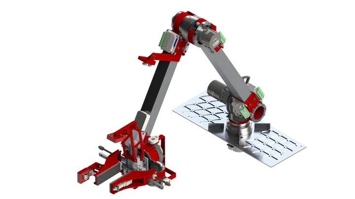
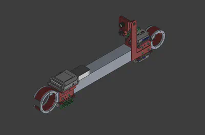
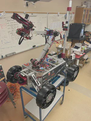
Overall Design
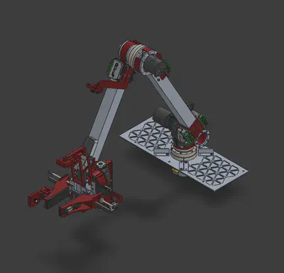
Electronics
The electronics essentially consisted of a fusebox, buck converter, motors, motor drivers, and cameras. I chose a 24V system, an upgrade from the previous 12V system, allowing higher torque density and cooler thermals. For the motors, I selected 24V brushless motors for a greater precision and efficiency despite more difficult controls.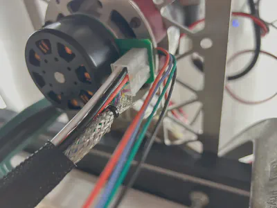
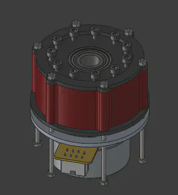
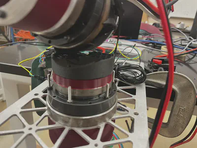
Gearboxes
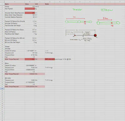
Each axis comprised a motor and a gearbox to produce the right amount of torque. I used strain wave gearboxes at the first three axes, which sustain the highest moment, and I used custom cycloidal gearboxes for the final three axes. These gearboxes were designed by a previous member but never successfully prototyped. I revised and tested them.
Materials
For the materials selection, I considered that my machining capability consisted of a CNC router and 3D printers, along with other simple machines like bandsaws, drill presses, and bench grinders. Consequently, I chose a 6061-T6 aluminum frame, making it light, sturdy, and machinable. I performed FEA on structural parts to ensure safety under expected loads.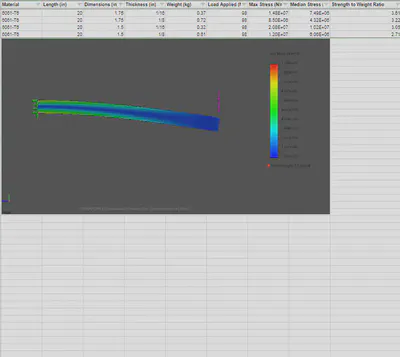
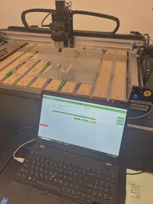
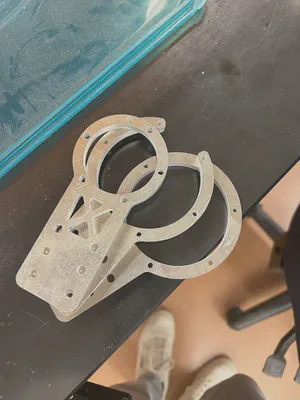
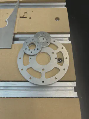
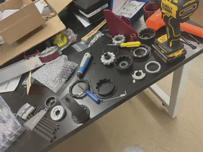
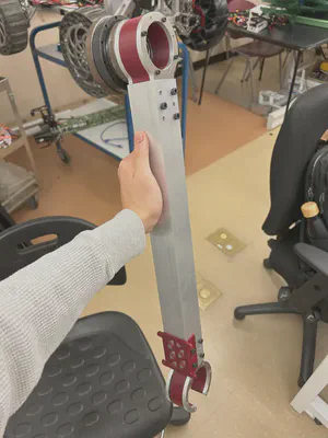
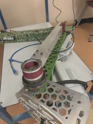
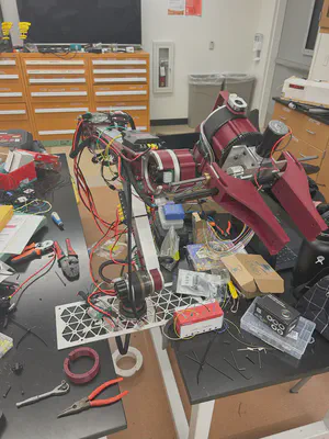
Manufacturing
I did most of the manufacturing and assembly for this arm, and it took me a couple months. Here are a couple images of the build!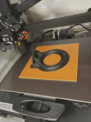
Testing
During testing, there were two critical failures.
First, one of the motors I chose proved to be too weak at the highest load axis. Solution? Bigger motor! And, bigger gearbox.
Second, the structural member at the shoulder fractured because I did not think hard enough about the design of the shoulder. I had suspected that it would break, but unfortunately left the problem for later. It was a carbon-fiber nylon 3D printed part, but the orientation of the print made it very weak, and a 3D print was nowhere strong enough for this application.
Solution? Design some parts out of metal.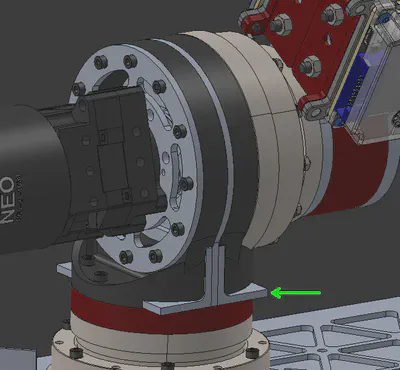
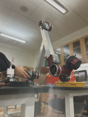
After those fixes, we were able to get out and start testing. We had several testing runs, but my favorite was carrying this lantern after sunset: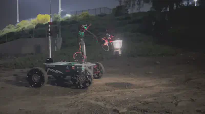
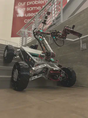
Finally, here’s a picture of this arm beside the arm I designed last year!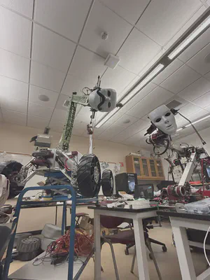
Competition
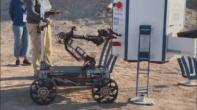
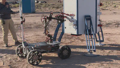
After acceptance into the final competition in Utah for the University Rover Challenge, the rover competed in two missions that involved the arm: the Delivery mission, a long range and intensive task involving search and delivery of heavy objects, and the Equipment Servicing Mission, a mission involving precise movements. We did great in both of them.
Here are some images from the Delivery Mission (5th place):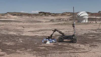


Here are some images from the Equipment Servising Mission (11th place):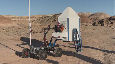
And here’s my favorite glory shot of our rover: